
Home › Products › Low pressure valves › Butterfly valves › Ductile iron wafer
Ductile iron - wafer type - stocked 2 inch to 4 inchDuctile iron wafer type butterfly valve, 2" to 4"
The wafer body that fits four flange standards — PN10, PN16, ANSI 150# and JIS 10K drilling in one valve. Ductile iron body, CF8 disc, EPDM seat, clamped between your pipe flanges.
The ductile iron wafer type
The tougher body in our butterfly range.
A resilient‑seated butterfly valve with a ductile iron body, a CF8 cast stainless disc on an SS410 shaft, and an EPDM seat liner — the same construction as the cast iron wafer type, in a body with far higher tensile and impact strength. Designed, dimensioned face‑to‑face and tested to API 609 / API 598.
We stock 2" to 4" (DN50 to DN100); the catalogue publishes 1½" to 6" and the other sizes can be brought in.
- Drilled to sit inside four flange standards — PN10, PN16, ANSI 150# and JIS 10K — so one stocked valve covers mixed pipework. The table publishes the drilling for all four. That is the reason to pick this body over the ANSI‑only cast iron wafer.
- ⚠ A wafer body cannot sit at the end of a line. It is held only by the bolts passing either side of it. For dead‑end service use the ductile iron lug type.
- Ductile iron takes shock and pipe loads that grey cast iron will not — the usual pick where a line vibrates, gets walked on, or sees water hammer.
- ⚠ Two different rubbers, with opposite compatibility. The seat is EPDM and the shaft O‑ring is NBR. The catalogue lists the medium as general oil, gas and water, as printed — but EPDM is poor with mineral oil and it is the pressure boundary, so tell us the fluid before you order. The compatibility table.
- ⚠ Check disc clearance before bolting up. On the smaller sizes the disc swings past the body face as it opens and can foul a reducer, a pump flange or a lined pipe.
- No gaskets against the pipe flanges. The EPDM seat has raised faces that seal directly against them; an extra gasket makes the joint worse.
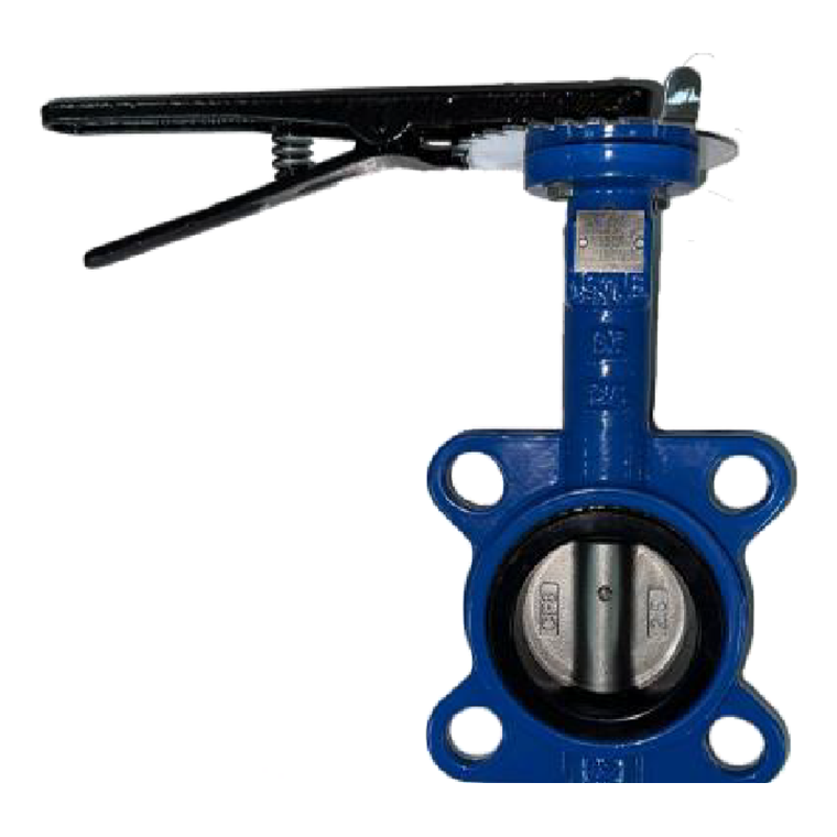
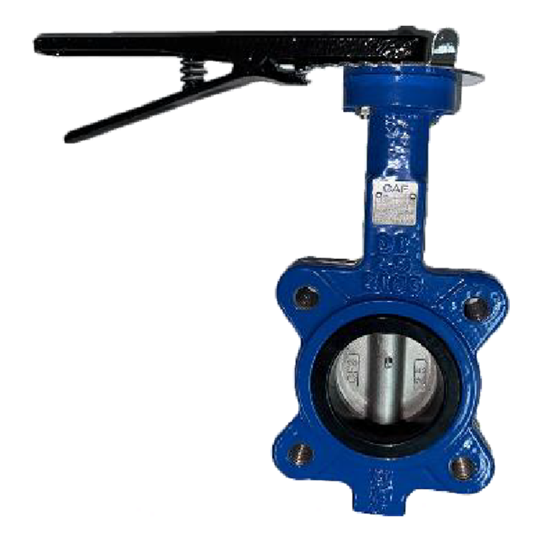
The stocked valve, photographed. From the manufacturer’s catalogue.
Specification
Everything that goes on a purchase order.
| Stocked sizes | 2" to 4" (DN50 to DN100) · catalogue publishes 1½" to 6" |
| Body style | Wafer type — also stocked as the ductile iron lug type and in cast iron |
| Drilling | PN10 · PN16 · ANSI 150# · JIS 10K — one body, four standards |
| Body | Ductile iron |
| Disc | CF8 in the bill of materials; SS304 in the part descriptions — the same 304 family, stated both ways |
| Seat | EPDM — and it is the pressure boundary |
| Shaft | SS410, pinned with SS304, in polymer bushings |
| Shaft seal | NBR O‑ring |
| Handle | Ductile iron lever with a notched locking plate |
| Design · face‑to‑face · testing | API 609 · API 609 · API 598 |
| Working pressure | 150 PSI per the catalogue · nominal 1.0 MPa per the test table — read them below |
| Working temperature | −30 °C to 120 °C |
| Parts in the list | 8 — identical on both body styles |
| Catalogue | Wafer type PDF — direct download below |
| Stock | Held in Malaysia or Singapore |
Bill of materials
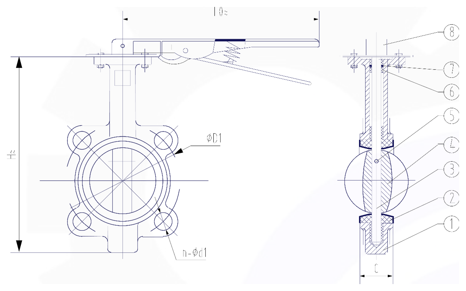
8 parts — identical on the wafer and lug bodies.
| No | Part name | Material |
|---|---|---|
| 1 | Body | Ductile iron |
| 2 | Seat | EPDM |
| 3 | Shaft | SS410 |
| 4 | Disc | CF8 |
| 5 | Pin | SS304 |
| 6 | Bushing | Polymers |
| 7 | Oring | NBR |
| 8 | Handle Lever | Ductile iron |
The manufacturer’s sectional drawing. Callout numbers correspond to the parts list above.
- ⚠ The seat is the part to specify. EPDM suits water, hot water and air and is poor with mineral oil. A different liner is a specification, not a modification — say so before you order.
- The disc is stated two ways in the source — CF8 in the bill of materials, SS304 in the part descriptions. Both are the 304 family; we quote both as printed.
- Part numbers run VL‑BU‑DI‑W‑24 to ‑96 (1½" to 6"), as printed. The stocked sizes are ‑32, ‑40, ‑48 and ‑64 (2" to 4").
Sizes and dimensions
Seven sizes, as the catalogue prints them. Dimensions in millimetres.
| DN | Size | Height H | Disc C | L0 (a) | L0 (b) | PN10 D1 | PN10 n‑d1 | PN16 D1 | PN16 n‑d1 | ANSI 150 D1 | ANSI 150 n‑d1 | JIS 10K D1 | JIS 10K n‑d1 |
|---|---|---|---|---|---|---|---|---|---|---|---|---|---|
| 40 | 1 1/2" | 241 | 42 | 240.4 | 220 | 110 | 4-18 | 110 | 4-18 | 98.5 | 4-16 | 105 | 4-19 |
| 50 | 2" | 241 | 42 | 240.4 | 220 | 125 | 4-18 | 125 | 4-18 | 120.5 | 4-19 | 120 | 4-19 |
| 65 | 2 1/2" | 264 | 44.7 | 240.4 | 220 | 145 | 4-18 | 145 | 4-18 | 139.5 | 4-19 | 140 | 4-19 |
| 80 | 3" | 276 | 45.2 | 240.4 | 220 | 160 | 4(8)-18 | 160 | 4(8)-18 | 152.5 | 4-19 | 150 | 4(8)-19 |
| 100 | 4" | 314 | 52.1 | 280.8 | 255 | 180 | 4(8)-18 | 180 | 4(8)-18 | 190.5 | 4-19 | 175 | 4(8)-19 |
| 125 | 5" | 310 | 54.4 | 280.8 | 260 | 210 | 4(8)-18 | 210 | 4(8)-18 | 216 | 4-22 | 210 | 4(8)-23 |
| 150 | 6" | 365 | 55.8 | 280.8 | 260 | 240 | 4(8)-23 | 240 | 4(8)-23 | 241.5 | 4-22 | 240 | 4(8)-23 |
- The table prints two L0 columns, as published — we reproduce both rather than guess which is which. If lever clearance is tight, ask and we will measure a stocked unit.
- ⚠ Bolt counts: take them from the flange standard. The PN and JIS columns print 4(8) from 3" up; the ANSI column prints 4 at every size, as published, where ASME B16.5 Class 150 uses 8 bolts from NPS 4 upward. On a wafer body those bolts clamp the valve in place.
- ⚠ One height figure runs backwards, as printed: H = 314 at 4" and 310 at 5". We publish it as the catalogue has it and will measure a stocked unit on request.
- ⚠ Leave clearance for the disc, not just for the body. On the smaller sizes the disc protrudes past the body face when open.
Test pressure and temperature
As the wafer type catalogue prints them.
| Nominal pressure | 1.0 MPa (145 PSI) |
| Shell test | 1.5 MPa |
| Sealing test | 1.1 MPa |
| Working temperature | −30 to 120 °C |
| Working pressure, features page | 150 PSI |
- The published nominal is 1.0 MPa (145 PSI), which sits consistently with the 150 PSI on the features page — and the shell and sealing tests are the usual 1.5× and 1.1× of it. The lug type’s catalogue prints a different nominal; each page carries its own figures as printed.
- ⚠ Shell and sealing tests are proof tests, not working pressures. Do not design to them.
- −30 to 120 °C is the rubber, not the iron. The EPDM seat and NBR O‑ring set the ceiling. For hot duty use a metal‑seated gate valve.
Questions we get asked
The ones that come up on the phone.
How is this different from the cast iron version?
The body is ductile iron, which has far higher tensile and impact strength than grey cast iron — the pick where a line vibrates or sees water hammer. The internals — CF8 disc, SS410 shaft, EPDM seat, NBR O‑ring — are the same as the cast iron wafer type. And this wafer body is drilled for four flange standards where the cast iron one is ANSI only.
Wafer or lug?
Lug if the valve is near the end of a line — its tapped holes let each flange bolt on independently, so the downstream pipe can come off with the valve holding pressure. A wafer body is clamped between two flanges and cannot do that — but the ductile iron wafer is the one drilled for four flange standards. This page is the wafer; the lug type is here.
Which sizes do you stock?
2" to 4" (DN50 to DN100), held in Malaysia or Singapore. The catalogue publishes 1½" to 6" — the other sizes can be brought in; tell us the quantity and the date you need them.
Is it 150 PSI?
The catalogue states 150 PSI working pressure, and its test table prints a nominal of 1.0 MPa (145 PSI). Those two sit consistently together. We publish everything as printed: design to 150 PSI unless we confirm otherwise.
Can I use it on oil?
The catalogue lists the medium as general oil, gas and water, as printed — but the seat is EPDM, which swells in mineral oil, and on a butterfly valve the seat is the pressure boundary. Our advice: water and air yes; oil, use a ball valve — or tell us the exact fluid and we will confirm the seat with the factory.
Which flange standard should I order it for?
You do not have to choose — that is the point. The body is drilled to sit inside PN10, PN16, ANSI 150# and JIS 10K bolt patterns; the table gives D1 and the hole pattern for each. Just take the bolt count and circle from your flange standard, not from the table’s ANSI column, which prints 4 at every size as published.
Can I fit an actuator or gearbox?
The wafer table does not print top‑flange columns, as published — the fitting looks identical to the lug type’s in the drawing, and we confirm it against a stocked unit before you order an actuator.
Does it need flange gaskets?
No, and they make the joint worse. The EPDM seat has raised faces that seal directly against the pipe flanges. Bolt the flanges straight onto the seat and pull up evenly.
Catalogue
Direct PDF download — no form, no email address.
Send the size and the fluid
We will confirm the EPDM seat suits what is in your line, check the drilling against your flange standard, and quote a landed price. Stock in Malaysia and Singapore.